|
|
|
Who's Online
There currently are 6025 guests online. |
|
Categories
|
|
Information
|
|
Featured Product
|
|
|
 |
|
|
There are currently no product reviews.
 ;
This service manual of the old video cassette recorder VT-LC50EM is very good readable even the tiniest numbers (i.e. IC-pins). The circuits are very clear. Many details of the schematic are very good described but in GERMAN language. Many schematic details - but complete at all. Common background information of several details are enclosed and physical knowledge of the TFT liquid crystal display for example. The manual lacks PCB drawings. If you understand german I would recommend this manual for you.
;
Hi, this is a very clear manual, nice copy, not quite up to the standard of the very best available but better than many others. I think the price was especially fair for a hard to find manual and I would certainly use this manual seller again. Recommended.
 ;
This schema available for me in good condition. I would highly recommend.
;
Thanks for this "hard to find" service manual.
I apreciate the good quality of scanning and the pages scanned in A3 format.
;
Helpd me mont a new carradio when prewius mont was a mess.
� Safety Check after Servicing
Examine the area surrounding the repaired location for damage or deterioration. Observe that screws, parts and wires have been returned to original positions. Afterwards, perform the following tests and confirm the specified values in order to verify compliance with safety standards. 1. Insulation resistance test Confirm the specified insulation resistance or greater between power cord plug prongs and externally exposed parts of the set (RF terminals, antenna terminals, video and audio input and output terminals, microphone jacks, earphone jacks, etc.). See table below. 2. Dielectric strength tes Confirm specified dielectric strength or greater between power cord plug prongs and exposed accessible parts of the set (RF terminals, antenna terminals, video and audio input and output terminals, microphone jacks, earphone jacks, etc.) See table below. 3. Clearance distance When replacing primary circuit components, confirm specified clearance distance (d), (d') between soldered terminals, and between terminals and surrounding metalic parts. See table below.
Table 1: Rating for selected areas AC Line Voltage 100V 110 to 130V * 100 to 250 V Region Japan USA & Canada South America Insulation Resistance � 1 M�/500 V DC ���
Fig. 1 Dielectric Strength 1kV 1 minute 900V 1 minute Clearance Distance (d), (d') � 3 mm � 3.2mm � 6 mm (d) � 8 mm (d') (a: Power cord)
� 10 M�/500 V DC
4 kV 1 minute
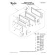
Note: This table is unofficial and for reference only. Be sure to confirm the precise values for your particular country and locality. 4. Leakage current test Confirm specified or lower leakage current between B (earth ground, power cord plug prongs) and externally exposed accessible parts (RF terminals, antenna terminals, video and audio input and output terminals, microphone jacks, earphone jacks, etc.) Measuring Method: (Power ON) Insert load Z between B (earth ground, power cord plug prongs) and exposed accessible parts. Use and AC voltmeter to measure across both terminals of load Z. See figure and following table. Fig. 2 Load Z Leakage Current (i) ¡ � 1m A rms ¡ � 0.5 m A rms ¡ � 0.7 m A peak ¡ � 2 m A dc ¡ � 0.7 m A peak ¡ � 2 m A dc
Earth Ground
Table 2: Leakage current ratings for selected areas
AC Line Voltage Region
100V 110 to 130 V
Japan USA & Canada South America
100 to 130 V 200 to 250 V
(B) to: Exposed accessible parts Exposed accessible parts Antenna earth terminals Other terminals
Note: This is table unofficial and for reference only. Be sure to confirm the precise values for your particular country and locality.
|
|
|
> |
|